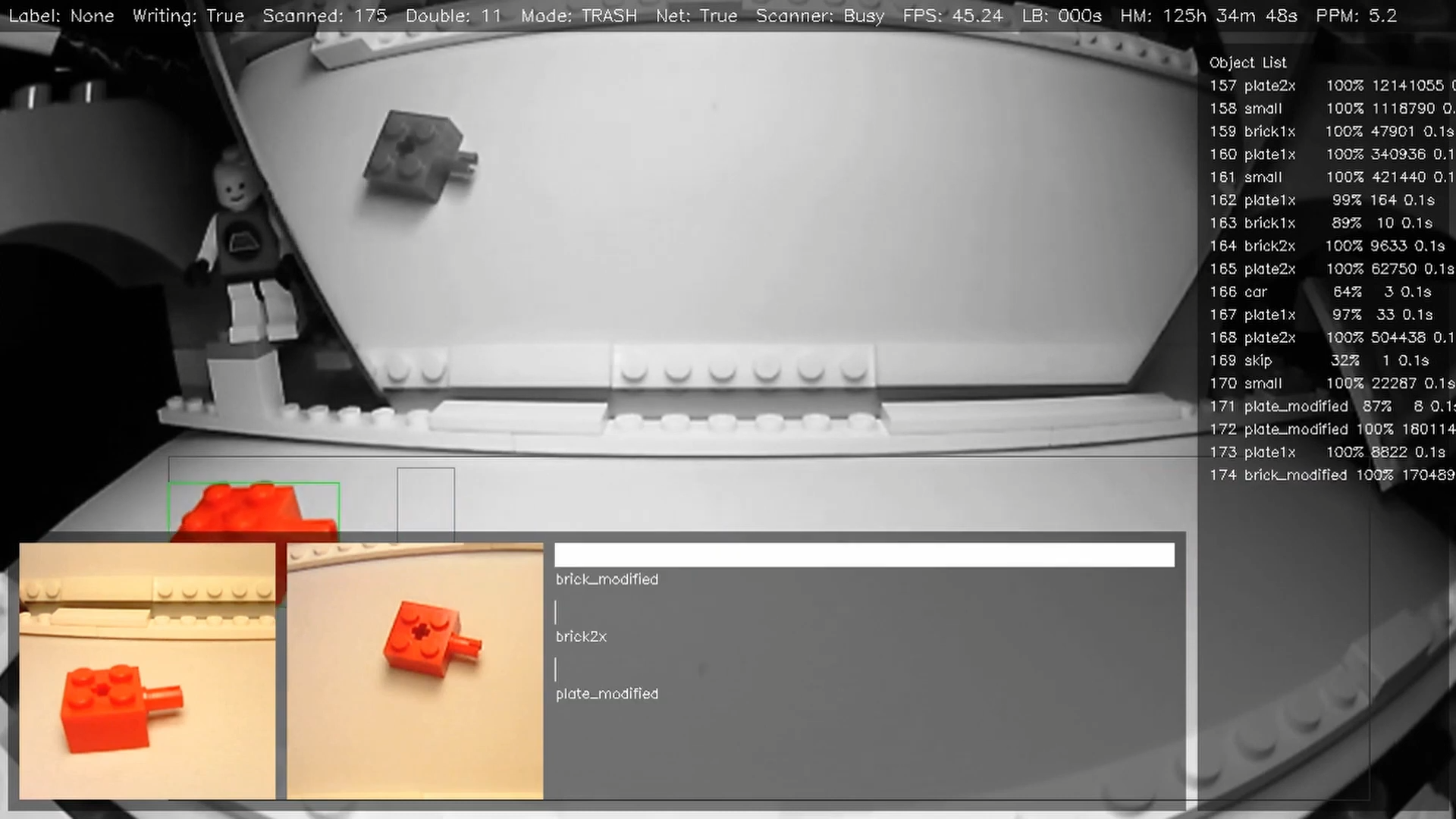

The motivation is straightforward: LEGO so far has produced approximately 20,000 different parts (including variations such as color). To advance sorting machines beyond handling part classes and enable sorting by individual part IDs, the number of discrete storage locations must strongly increase.
Storage approaches typically scale hardware needs linearly in the number of bins. For example, a belt-and-gate system requires one dedicated gate and servo for each storage location. This quickly becomes infeasible as the number of bins increases, leading to complex and expensive machines.
A Scalable Approach: Automated Storage and Retrieval Systems (AS/RS)
To overcome this limitation, I’m exploring an approach with more favorable scaling properties. It draws inspiration from large-scale warehouse storage, specifically Automated Storage and Retrieval Systems (AS/RS). These systems efficiently manage vast quantities of goods using automated cranes or shuttles to retrieve items from dense storage racks.
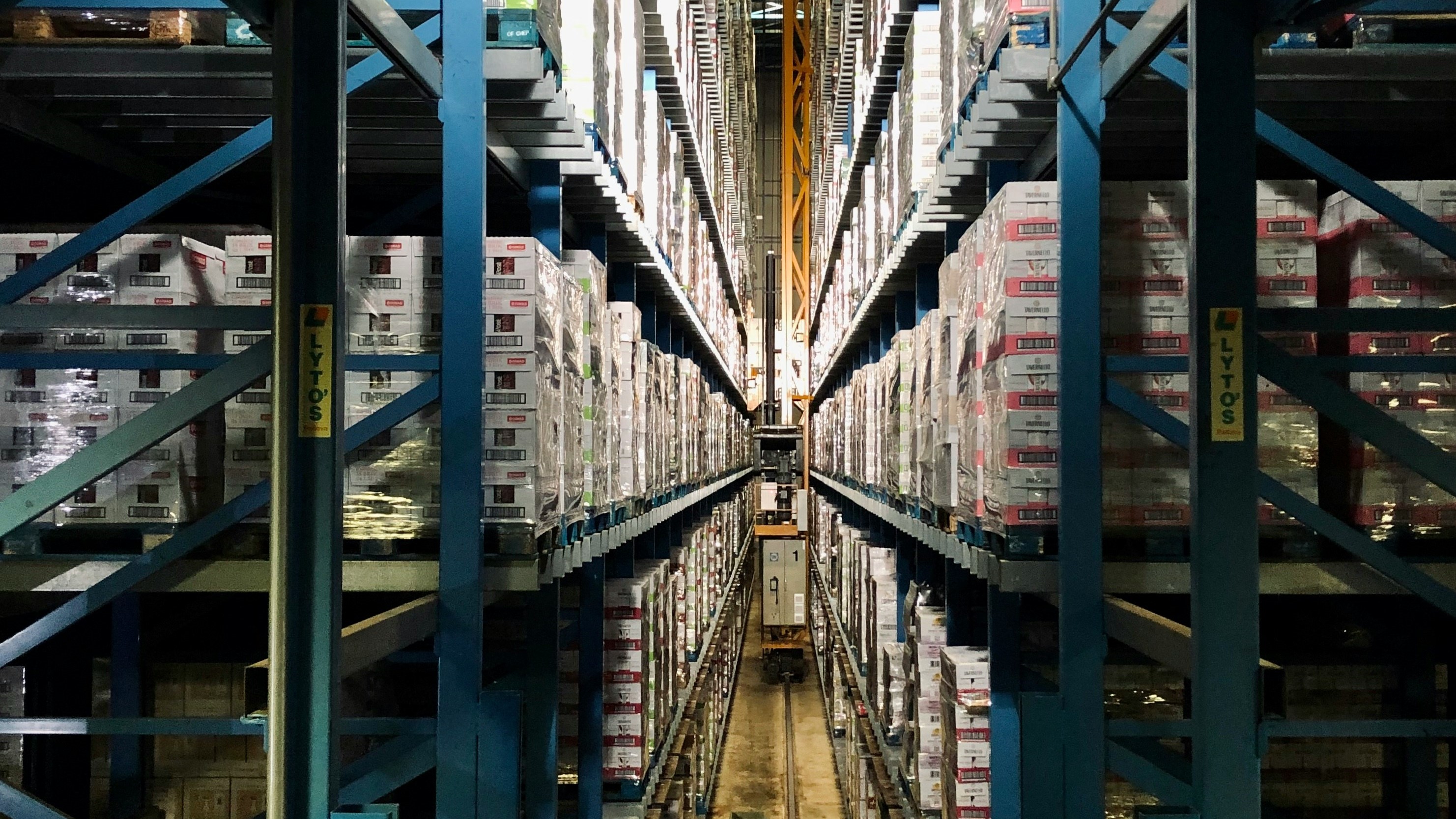 An automated highbay warehouse (photo by Arno Senoner on Unsplash)
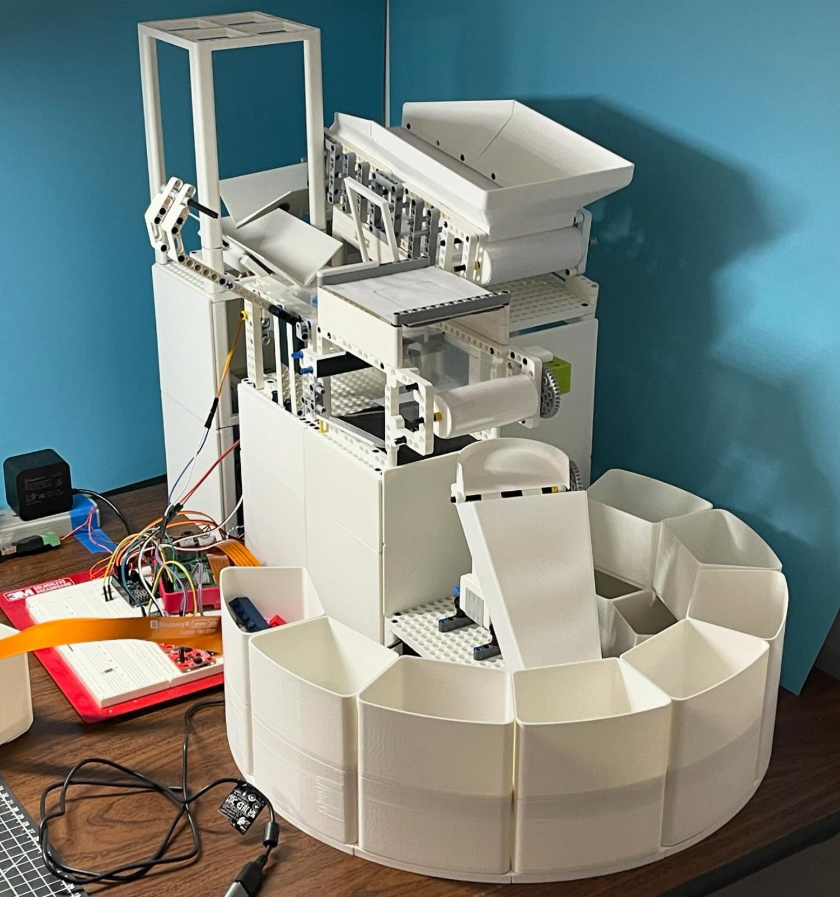
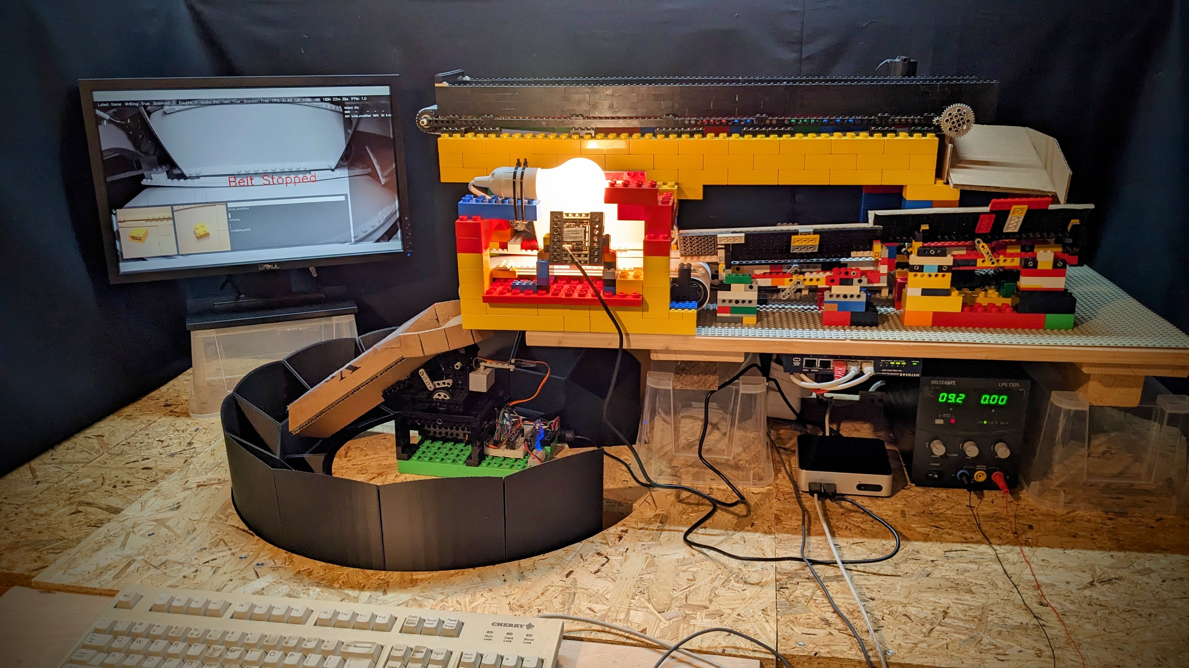
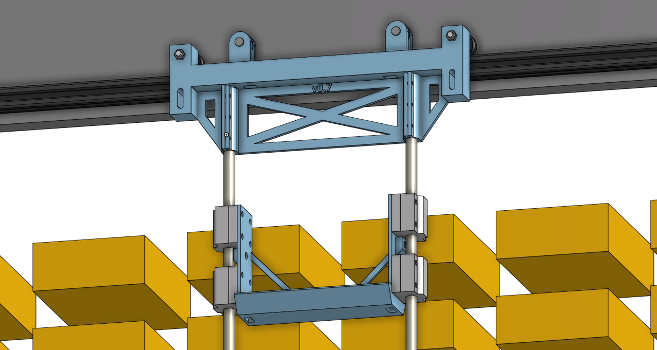
As a proof of concept, I plan to integrate a small-scale, DIY AS/RS with my existing LEGO brick sorting machine. The sorter will continue classifying parts as usual but will now instruct the storage system to retrieve the appropriate bin for depositing each part. The core idea is simple: If the DIY automated storage system can reliably manage 100 bins, scaling up to 1,000 bins—or even more—should be achievable by either increasing its physical size or deploying multiple AS/RS units side by side.
More importantly, this approach shifts the complexity from handling individual parts to moving entire bins, which not only simplifies automation but also enables instant part retrieval. For BrickLink sellers and advanced LEGO builders, this means dramatically faster access to specific parts. Instead of manually searching through drawers or containers, the system can fetch and deliver the required bin in seconds, streamlining the entire building and order fulfillment process.
Let me summarize the key requirements for this project:
- Scale - The system must support ≥100 storage bins, with the option for further internal subdivisions to accommodate smaller parts.
- Efficient Operation - The system should enable ≥10 storage operations per minute without introducing additional latency.
Design
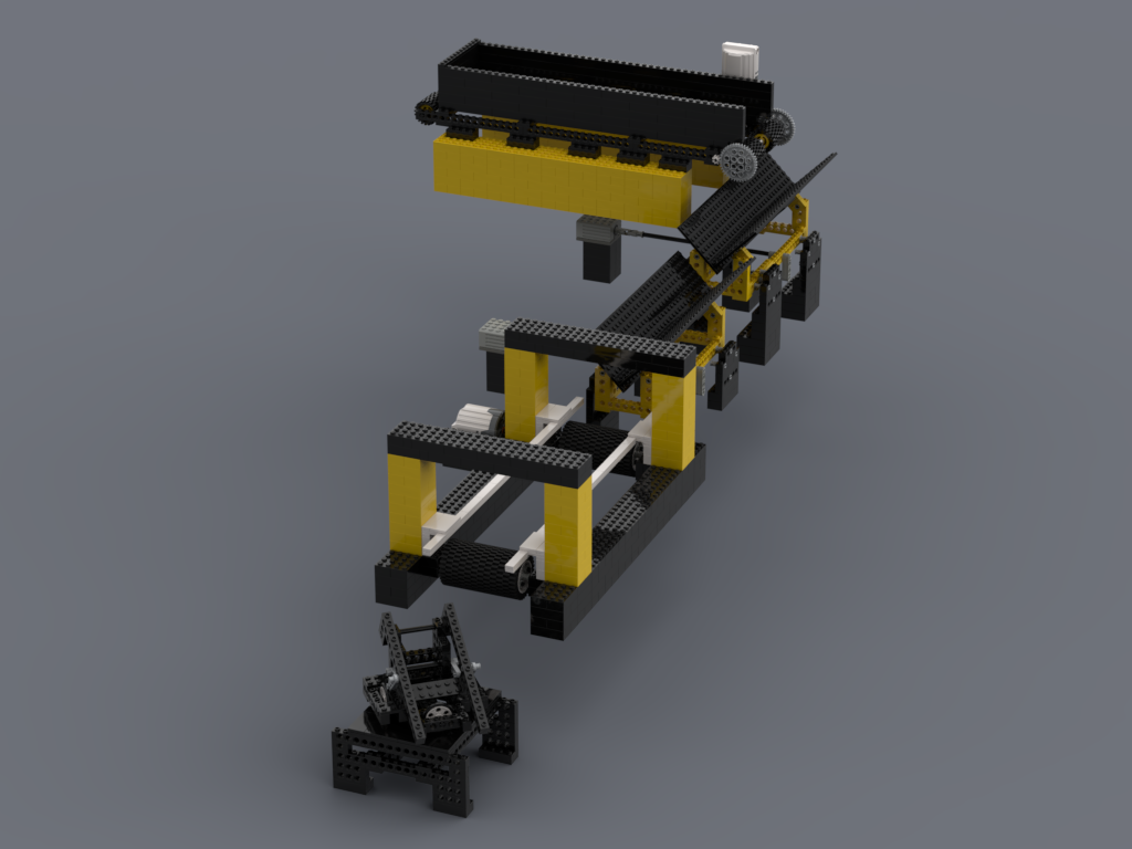
The design and construction of the AS/RS will revolve around three major components:
- Storage Rack - A structured shelving system to hold each storage bin in a 2D grid layout.
- Moving Gantry - A mechanism providing precise X/Y motion across the storage rack to access bins.
- Telescopic Fork - A retrieval mechanism that extends and retracts along the Z-axis, allowing bins to be pulled from / pushed to the rack.
Storage Rack
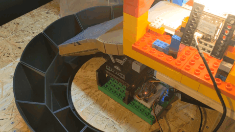
The storage rack serves as the structural backbone of the system, organizing bins in a grid layout for efficient retrieval. For storage bins, I have chosen off-the-shelf polystyrene sorting bins. Priced at just €1.70 per bin, they are cheap and at the same time available quickly. The bins measure 162mm x 108mm x 45mm. They are thus large enough to accommodate even bigger LEGO parts while at the same time allowing them to be further subdivided to maximize storage density for smaller parts.
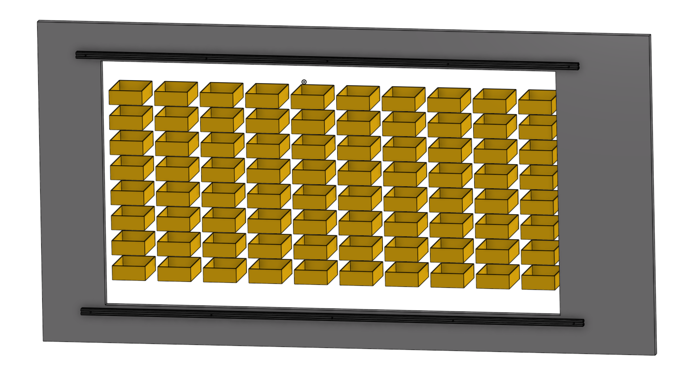

For the first prototype setup, I am targeting a 10-by-8 grid of bins. To ensure smooth retrieval, I’ve accounted for small gaps between bins, bringing the total estimated dimensions of the storage system to approximately 1.65m x 0.8m. This compact footprint is ideal, as it allows the unit to fit neatly behind the existing sorting machine while still providing high storage capacity.
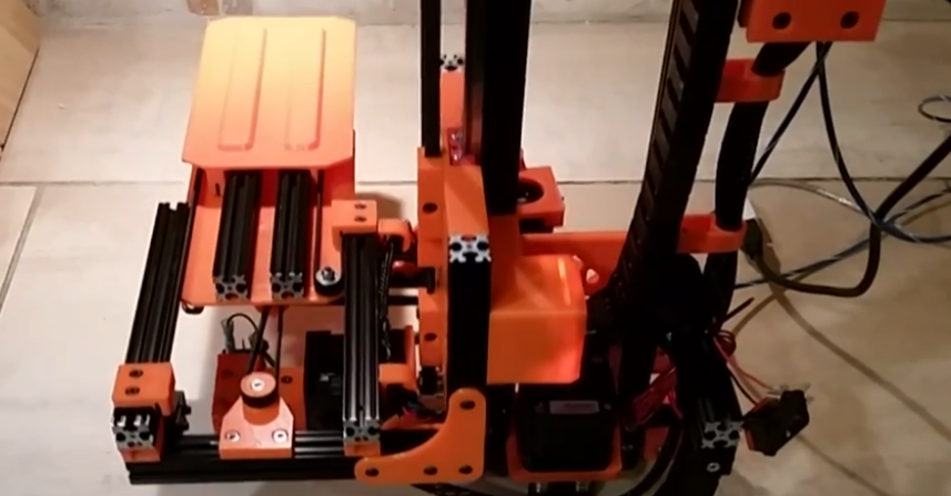
Gantry
The moving gantry is responsible for precise 2D motion across the storage rack, enabling the system to position itself over any bin. To achieve smooth and reliable movement, I drew inspiration from DIY CNC machines and 3D printers, which commonly rely on linear rails for accurate motion. However, full-length linear rails at the scale required for this project are prohibitively expensive, prompting me to explore more cost-effective alternatives.
For the vertical Y-axis, I opted for round linear bearings, which provide a reasonable balance between precision and affordability. These bearings allow smooth movement while keeping costs lower than premium linear rail systems.
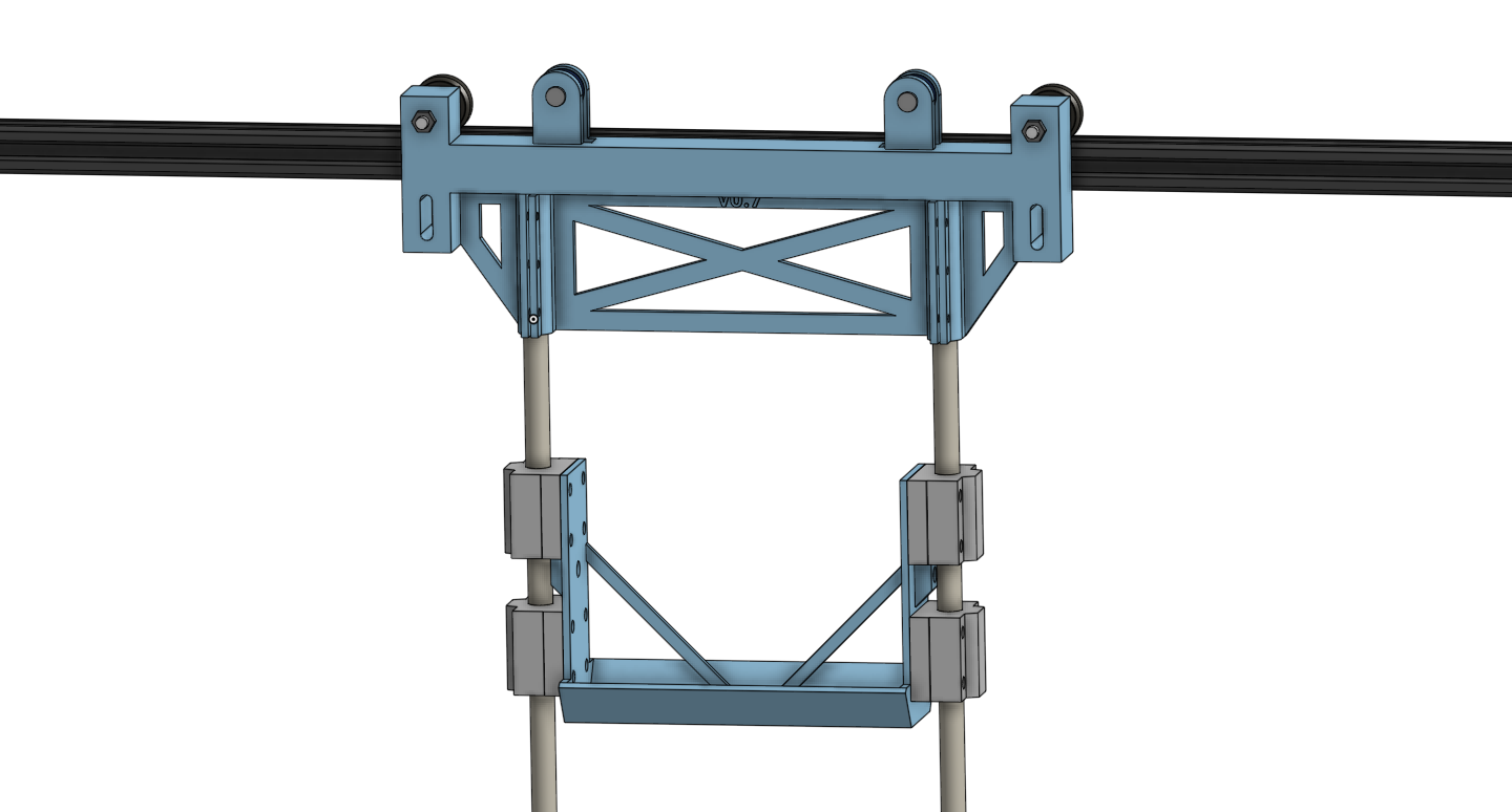
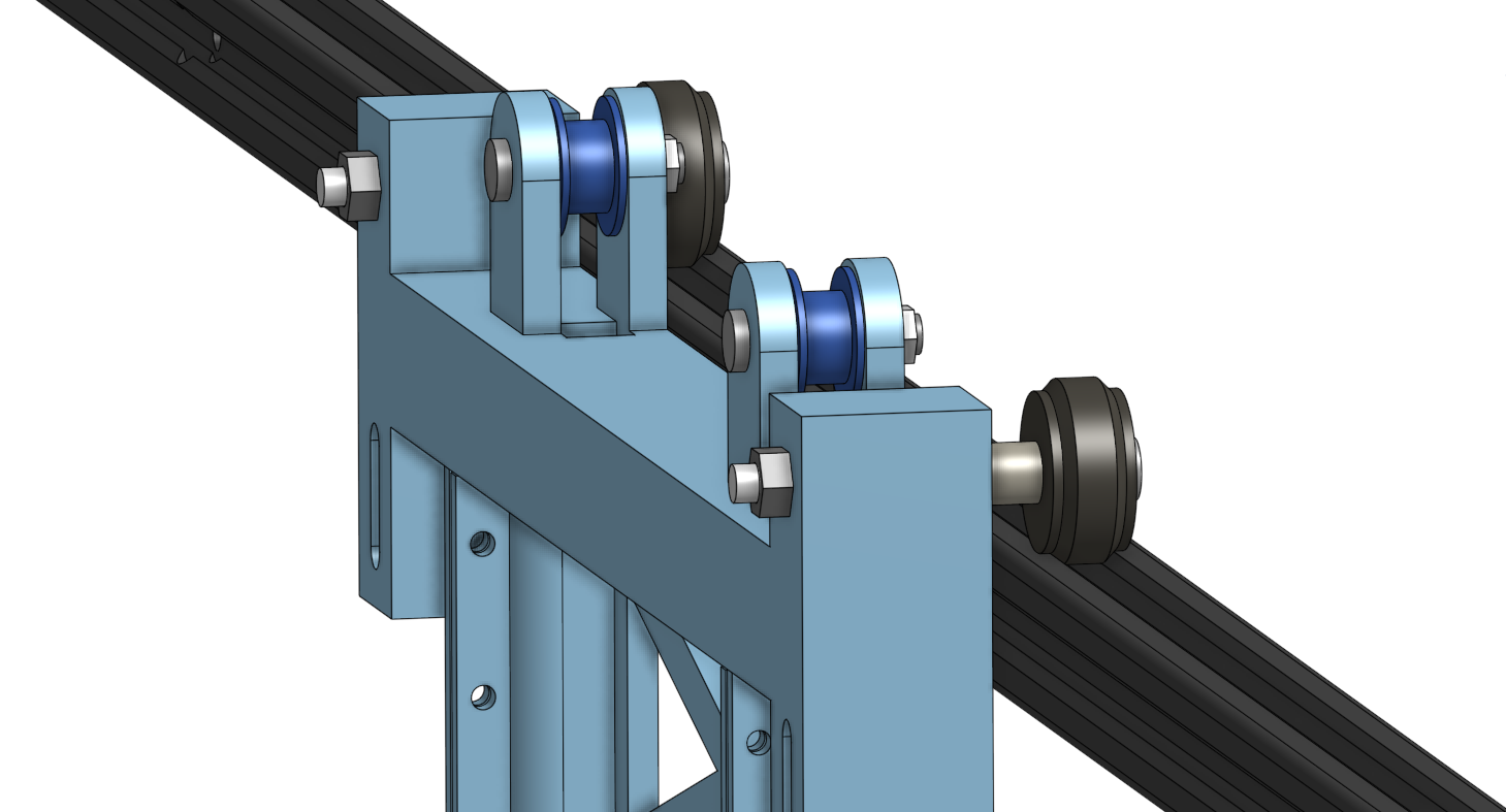
For the horizontal X-axis, which spans a significant length, I needed an even more budget-friendly yet effective solution. Drawing inspiration from entry-level 3D printers like the Ender 3, I chose 20mm x 20mm V-slot aluminium extrusions paired with matching rubber wheels that fit precisely into the V-slot profile. These components are readily available as off-the-shelf replacement parts for 3D printers, making them both cost-effective and easy to source. The wheels come as complete assemblies with pre-mounted bearings, screws, and spacers, simplifying integration into the gantry design.
The gantry’s wheel configuration is designed to ensure rigidity and maintain precise vertical alignment:
- Two wheels on top of the extrusion rail
- Two wheels below, running along the underside of the rail
This setup effectively prevents unwanted movement or wobble, ensuring the gantry remains stable as it moves across the storage rack. The two upper wheels bear the majority of the load, supporting the weight of the moving gantry assembly. To ensure long-term durability, I will closely monitor these wheels, their bearings, and their mounting points for any signs of wear. If necessary, I will reinforce the structure or integrate additional wheels to better distribute the load and enhance long-term reliability.
Beyond load-bearing considerations, the gantry must be exceptionally rigid, particularly against torsion and racking forces, which could cause misalignment. To address this, I designed it with a wide stance and rigid diagonal supports, improving structural integrity. The stainless steel rods of the vertical Y-axis are securely mounted at the gantry ends using press fittings, which are tensioned with small screws to ensure a stable connection. This setup enhances overall rigidity and minimizes flex during rapid movements.
 Gantry-end element reinforced for shearing forces
The telescopic fork, serving as the end-effector that interacts with the storage bins, requires an onboard stepper motor for its operation. Consequently, cables must be routed to the fork while allowing for unrestricted movement along both the X and Y axes.
To achieve clean and reliable cable management, I plan to incorporate miniature drag chains along the linear rails. These chains will guide and protect the cables, ensuring they move smoothly without tangling or excessive strain. However, in the current CAD design, these drag chains have not yet been included. My approach is to first build a prototype without them, allowing me to gain practical experience with the system before finalizing the cable routing.
The same iterative approach applies to end-stop switches, which are critical for automated homing and safe operation. These switches will enable the system to accurately reset its position upon startup, preventing misalignment or unintended movements. They will be added in later iterations as I refine the design based on real-world testing results.
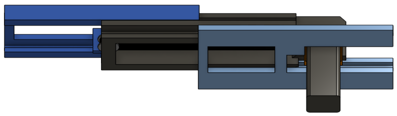
Telescopic Fork
The telescopic fork serves as the end-effector responsible for handling storage bins. Its retrieval process follows a three-step sequence:
- The fork extends beneath the designated bin, reaching into the storage rack.
- The gantry lifts the fork, raising the bin from its slot.
- The fork then retracts, carrying the bin along with it.
There is a wide range of DIY inspiration available showcasing various approaches to building a telescopic fork. The most common design mounts the motor on the stationary base, using a system of belts and pulleys to coordinate the movement of the telescoping segments. However, the Awesomemakes YouTube channel presents a more elegant solution: By mounting the motor to the middle segment of the fork, the design achieves a much simpler motion coupling. This approach reduces mechanical complexity and minimizes the number of moving parts.
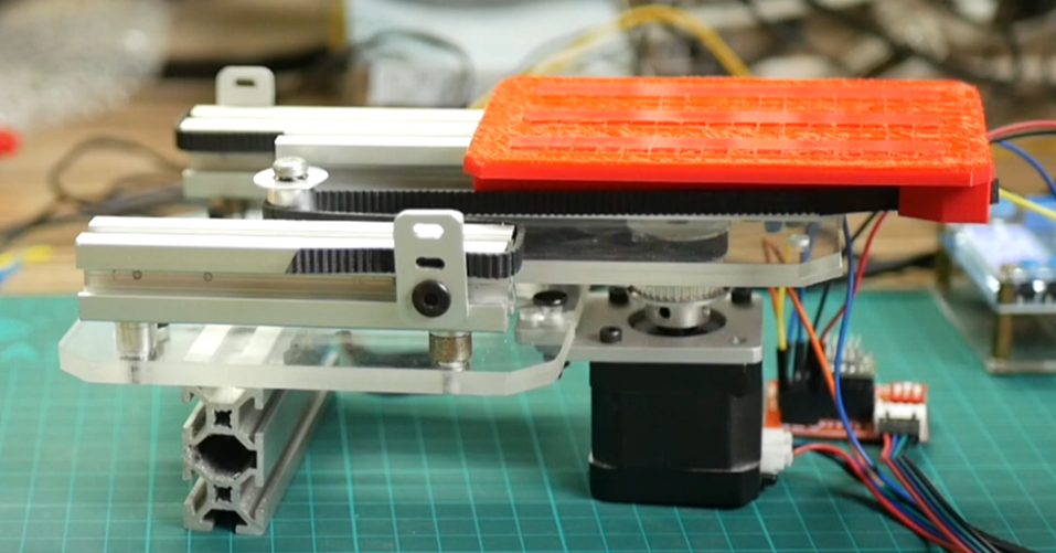
For my own design, I decided to combine both approaches: I will mount the motor to the middle segment to benefit from the simplified mechanics, but instead of using gears, I plan to use one belt to achieve synchronized motion between the elements.
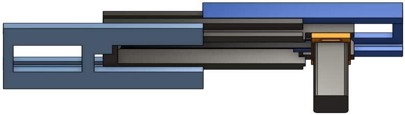
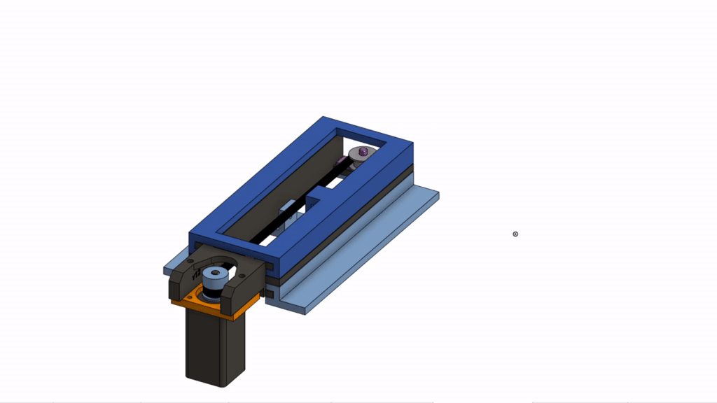 CAD drawing of the telescopic fork
The fork is constructed from five 3D-printed components: the base, middle, and top sliding segments, a motor mounting plate (orange), and a pulley holder (pink). The motor is rigidly attached to the mounting plate, which is itself fastened to the middle segment of the fork using elongated screw holes. These slots allow for precise adjustment of the motor position to tension the belt. The pulley holder (pink) is printed separately and is only glued in place after the three sliding segments have been nested together.
At this stage, the design does not incorporate any linear rails or bearings. Instead, it relies solely on PLA plastic surfaces sliding directly against each other. While this keeps the construction lightweight and simple, I’m uncertain about its long-term durability. This aspect will need to be closely monitored for wear over time.
In addition, the fit and tolerances between the sliding elements are critical: The parts must move with minimal friction while also maintaining tight alignment to prevent play. This is especially important when the fork is fully extended backward, as the motor (being the heaviest component) is positioned far behind the mounting point. This could introduce imbalance or sagging.
It is crucial to the overall design that the fork can extend in both directions—forward into the storage rack and backward toward the sorting machine. This bidirectional capability offers two key advantages:
-
Future Expandability – It opens the possibility of adding a second storage rack on the opposite side of the gantry. This would double the storage capacity without requiring any mechanical changes to the fork or gantry system. The same hardware could serve both sides, maximizing efficiency within the same footprint.
-
Precise Bin Positioning – Extending the fork toward the sorting machine also allows the system to precisely adjust the position of the bin during part insertion. This fine-grained control over where the LEGO piece lands within the bin will make it possible to implement internal subdivisions. Especially for small parts, this would significantly increase storage density by allowing multiple sub-compartments within a single bin, each dedicated to a different part or color variant.
Wrapping Up
This concludes the overview of the current AS/RS design work at the CAD level. Nearly all core components are designed, with some details still left open.
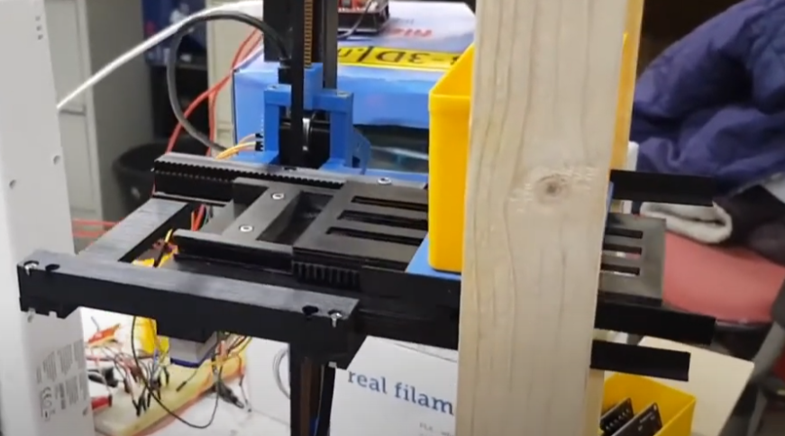
In parallel, I’ve already begun 3D printing for the physical prototype, testing key subsystems like the gantry mechanics, motor controllers and the telescopic fork in real-world conditions. These tests will provide lots of important early learnings.
I’ll be sharing an update on these tests very soon, here on the blog. Until then, feel free to reach out! I’m always happy to connect with fellow builders, makers, and curious minds — whether you have questions, suggestions, or just want to chat about LEGO sorter projects. The easiest way to reach me is via Discord or Instagram. Looking forward to hearing from you!
 CAD drawing of the automated storage and retrieval system (without z-axis)